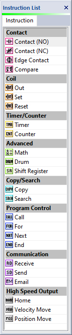
Contact Normally Open
The Normally Open Contact mimics the behavior of a physical contact and changes in response to the status of a Bit
Memory Address. The Normally Open Contact is ON when the related bit is ON.
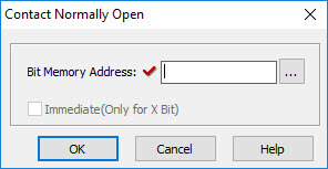
Contact Normally Closed
The Normally Close Contact mimics the behavior of a physical contact and changes in response to the status of a Bit Memory
Address. The Normally Closed Contact is OFF when the related bit is OFF.
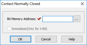
Edge Contact
The Edge Contact turns ON when the related bit transitions from OFF to ON (Rising Edge) or ON to OFF (Falling Edge).
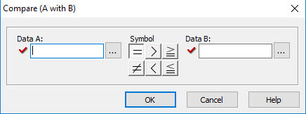
Compare Contact
The Compare A with B instruction uses a Mathematical Operator as a basis of comparison of two data values. A mathematical
statement is developed using the instruction dialog. When the Data A value satisfies the selected mathematical relationship
with Data B, the associated Bit Memory Address is turned ON.
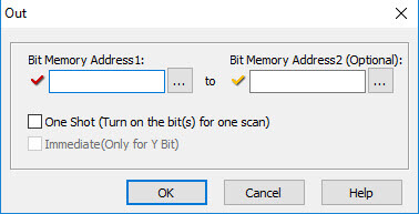
Out Coil
An Out instruction turns ON its associated Bit Memory when the status of the rung is true. The Out instruction turns OFF its
associated Bit Memory when the status of the rung is false. An Out instruction is capable of turning on and off more than one
Bit Memory Address at the same time.
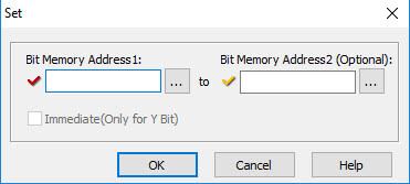
Set Coil
The Set instruction turns ON the associated Bit Memory when the status of the rung is true. The Set instruction can turn ON more
than one Bit Memory at the same time.
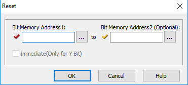
Reset Coil
The Reset instruction will turn off the associated bit memory when the status of the rung is true. A Reset instruction can turn
off more than one bit memory at the same time.
Timer
An ON Delay Timer measures a user-specified time duration that begins with a transition of the enable rung from OFF to ON. Beyond
this transition point, the Timer increases the Current Value until it reaches the Set Point, when the Timer Bit is turned ON.
An OFF Delay Timer measures a user-specified time duration that begins with a transition of the enable rung from ON to OFF. Beyond
this transition point, the Timer increases the Current Value reaches the Set Point, when the Timer Bit is turned OFF.
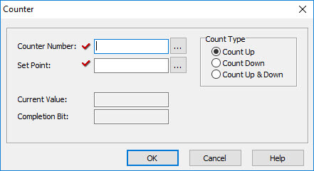
Counter
When enabled, a Counter instruction counts up or down (depending on user settings) until it reaches the Set Point. The Counter counts
in response to the transition from OFF to ON of the enabling rung. If the user selects Count Up & Down, the Counter will have two
enabling rungs, one for up counts and one for down counts.
The current count is held in the register shown in the Current Value field. When the Current Value reaches the Set Point, the
Completion Bit is turned ON. The Completion Bit is turned OFF when the Reset rung is enabled.
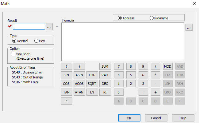
Math
The Math instruction serves as a powerful calculator to perform mathematical operations during the execution of the Ladder Program.
The formula area is used to develop the mathematical expression that will be solved during the CPU scan. The mathematical expression
can be developed using the onscreen keypad, the keyboard, and Address Picker, combining constants and stored variable values, as
necessary for the application.
Two sets of mathematical operators are available within the Math instruction: decimal and hexadecimal. When the Decimal radio button
selected,the available operators include: standard arithmetic and algebraic operators, parentheses for grouping terms, and
transcendental functions and operators. When the radio button for Hex is selected, the logical operators: AND, OR, XOR, and the bit
operations: Shift Left(LSH), Shift Right(RSH), Roll Left(LRO) and Roll Right(RRO) are made available. The Sum and Modulo operators
are available for either decimal or hexadecimal data values.
Parenthetical expressions can be nested up to eight levels deep. If the Floating Point Data Type is employed in any operation, then
all operations will be based on Floating Point math. The Result will be stored in the data format selected for the Result.
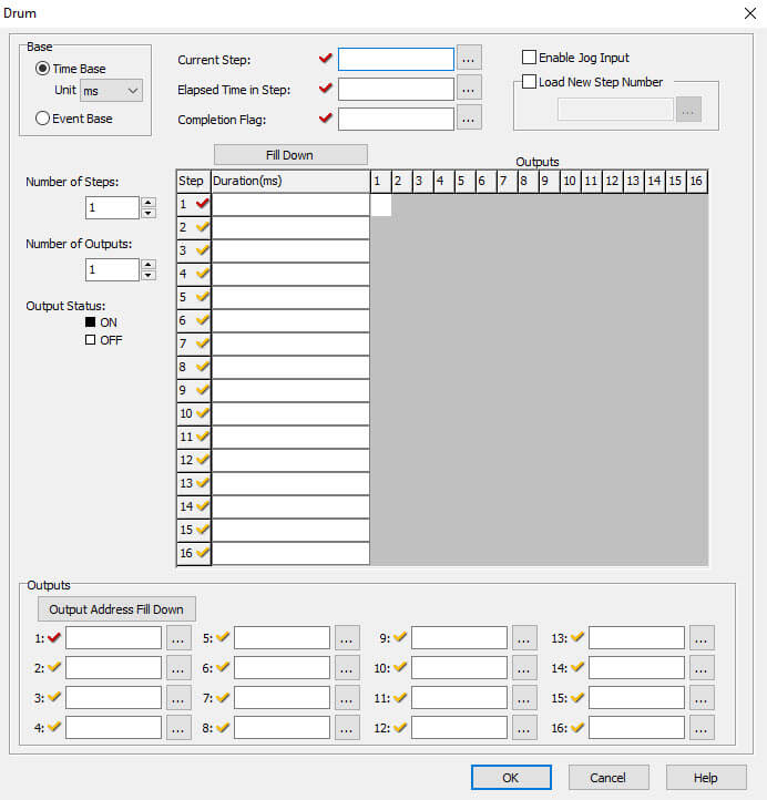
Drum
The Drum instruction is used to simulate an electro-mechanical drum sequencer. It works on time base or event base.
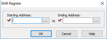
Shift Register
The Shift Register instruction shifts a range of control bits with each OFF-to-ON transition of the Clock pulse. If the starting
address is lower than ending address the shift register will shift from left to right. If the ending address is lower than starting
address then shift register will shift from right to left.
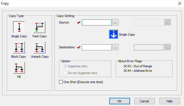
Copy
The Single Copy instruction is used to copy a value from its Source location to a specified Destination register. The Source location
can be another register, identified by its Memory Address, or a constant value entered in this dialog. The Block Copy option is used
to copy values from a block of Source locations to a block of Destination registers. The Source location of the data or text is
identified by a range of memory addresses, and only the first register of the destination range is required. The Block Copy opion
also allows the copying of numerical text values (strings) to one or more data registers as integer values.
The Fill option is used to copy a value from a single Source location to a specified range of Destination registers. The Source
location can be a register, identified by its Memory Address, or a constant value typed directly into the Source field in this dialog.
The Pack Copy mode combines the status of up to 16 Source Bit Memory Addresses (X, Y, C, T, CT or SC) and copies the combined status
into a Destination Data Register (DH or YD).
The Unpack Copy mode copies the data in a Source Data Register (DH only) to up to 16 Destination Bit Memory Addresses (Y or C).
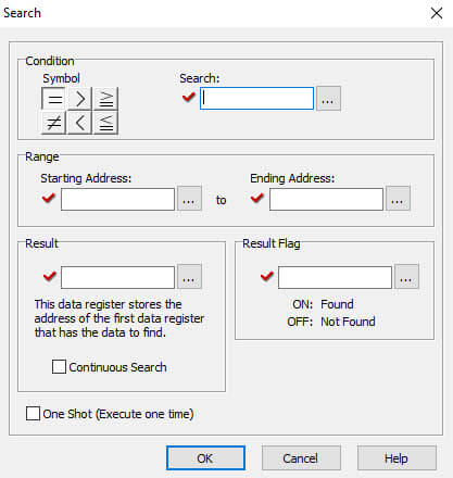
Search
The Search instruction is used to search for a data value that meets specified conditions and that is located within a specified
range of data registers. A successful search returns the Memory Address of the value that satisfies the conditions.
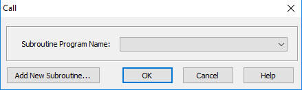
Call Instruction
The Call instruction is used to call a Subroutine program from the Main Program. The Call instruction resides in the Coil Area of
the Ladder Program. A Subroutine program must have a Return instruction to return to the Main Program.
Return
There is no dialog box needed for the Return Instruction, the instruction is either inserted at the current rung, or it can be
"dragged and dropped" at the desired position. All Subroutine programs must have at least one Return instruction to
return to the Main Program. The Return instruction resides in the Coil Area of the subroutine program..
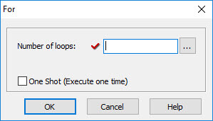
For Instruction (For-Next Loop)
The For instruction indicates the starting point of a For - Next loop, and based on its user setting, determines how many times
the For - Next loop will be executed. Between the For instruction rung and the Next instruction rung, place the rungs of logic that
should be repeated multiple times. Placing one For-Next loop inside another For-Next loop is not permitted.
Next Instruction (For-Next Loop)
The Next instruction doesn't need a dialog box, the instruction is either inserted at the current rung, or it can be "dragged
and dropped" at the desired position. The Next instruction indicates the end of a For loop. The ladder program will either
loop or continue depending on the settings of the consesponding For Instruction. The Next instruction must be the only instruction
on its rung. No enabling contacts are allowed on the same rung with the Next instruction.
End Instruction
The End instruction doesn't need a dialog box, the instruction is either inserted at the current rung, or it can be "dragged
and dropped" at the desired position. The End instruction indicates the end of the Main Ladder Program. No ladder code is
allowed beyond the End Instruction.
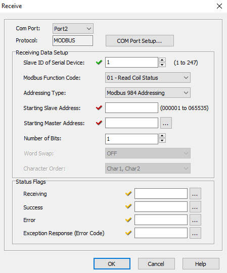
Receive
The Receive Instruction accepts Modbus or ASCII communications to your ladder program.
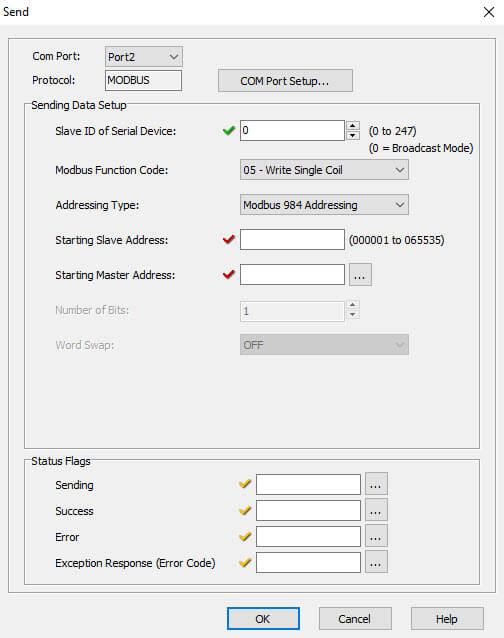
Send
The Send Instruction allows your ladder program to send Modbus or ASCII communications to other devices.


 Safe &
Secure
Safe &
Secure


